Corridor

Feature Definition
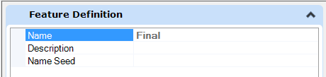
The common fields for Name, Description and Name Seed are supported.
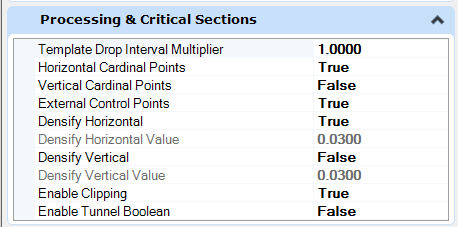
Processing and Critical Sections
|
Option |
Description |
|
The Template Drop Interval Multiplier is used in conjunction with the Interval Drop specified when the template drop was created. Its purpose is to enable designers to use larger intervals for preliminary work and easily shorten the interval as the design is refined. To determine the interval used for processing, the Interval Drop is multiplied by the Template Drop Interval Multiplier and the result is used. |
|
|
Horizontal Cardinal Points |
When set to True, the location of cardinal points of the active horizontal alignment (PC, PT, CS, etc.) are used to compute a point or template drop interval location. |
|
Vertical Cardinal Points |
When set to True, the location of cardinal points of the active vertical alignment (VPC, VPT, VPI, etc.) are used to compute a point or template drop interval location. |
|
External Control Points |
When set to True, the location of horizontal and/or vertical point controls are used compute a point or template drop interval location. |
|
Densify Horizontal |
When set to true, the processing along horizontal curves is at a closer interval. This option utilizes the CIVIL_DEFAULT_CURVE_STROKING configuration variable value, with extra points being computed based on the chord offset from the horizontal curve. |
|
Densify Horizontal Value |
The value defines the chord height used to calculate the extra points. If configuration variable is not set or Densify Horizontal Curves is set to False, the value defaults to 0.01. |
|
Densify Vertical |
When set to true, the processing along vertical curves is at a closer interval. This option utilizes the CIVIL_DEFAULT_PROFILE_STROKING setting, with extra points being computed based on a chord offset from the profile. |
|
Densify Vertical Value |
The value defines the chord height used to calculate the extra points. If the configuration variable is not set or Densify Vertical Curves is set to False, the value defaults to 0.1. |
|
Enable Clipping |
Enables or prevents the printing system from sending clip fences to the printer driver. If this property is not defined, the printing system uses True. When set to True the corridor will allow clipping using civil cells, shapes, solids, meshes, etc. |
|
Option |
Description |
|
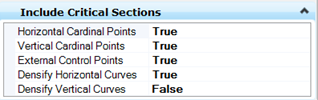
Horizontal Cardinal Points |
When set to True, the location of cardinal points of the active horizontal alignment (PC, PT, CS, etc.) are used to compute a point or template drop interval location. |
|
Vertical Cardinal Points |
When set to True, the location of cardinal points of the active vertical alignment (VPC, VPT, VPI, etc.) are used to compute a point or template drop interval location. |
|
External Control Points |
When set to True, the location of horizontal and/or vertical point controls are used compute a point or template drop interval location. |
|
Densify Horizontal Curves |
When set to true, the processing along horizontal curves is at a closer interval. This option utilizes the CIVIL_DEFAULT_CURVE_STROKING configuration variable value, with extra points being computed based on the chord offset from the horizontal curve. The value defines the chord height used to calculate the extra points. If configuration variable is not set or Densify Horizontal Curves is set to False, the value defaults to 0.01. |
|
Densify Vertical Curves |
When set to true, the processing along vertical curves is at a closer interval. This option utilizes the CIVIL_DEFAULT_PROFILE_STROKING setting, with extra points being computed based on a chord offset from the profile. The value defines the chord height used to calculate the extra points. If the configuration variable is not set or Densify Vertical Curves is set to False, the value defaults to 0.1. |
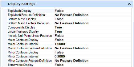
Display Settings
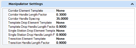
Manipulator Settings
|
Option |
Description |
|
Corridor - Element Template |
Element template utilizes to draw the corridor boundary in the Create Corridor tool. As a best practice, place the graphics for the boundaries in a construction class to allow for easily turning them off / on as needed. |
|
Corridor Handle Length Factor |
The Length Factors are a ratio of the handle length to the width of the corridor. So 1.0 would make the handle as long as the width of the corridor at that point. |
|
Corridor Handle Spacing |
The handle spacing either is set to a physical distance as shown or set to zero. If you set to zero you will get 11 handles per corridor regardless of its length. Any non-zero value is used as a distance between handles measured in master units along the horizontal alignment. |
|
Template Drop Element Template |
Element template utilized to draw the template drop boundary in the Create Template Drop tool. As a best practice, place the graphics for the boundaries in a construction class to allow for easily turning them off /on as needed. |
|
Template Drop Handle Length Factor |
The Length Factors are a ratio of the handle length to the width of the corridor. So, 1.0 would make the handle as long as the width of the corridor at that point. |
|
Single Station Drop Element Template |
The Length Factors are a ratio of the handle length to the width of the corridor. So, 1.0 would make the handle as long as the width of the corridor at that point. Element template utilized to draw the transition boundary in the Create Transition tool. As a best practice, place the graphics for the boundaries in a construction class to allow for easily turning them off /on as needed. |
|
Transition Element Template |
|
|
Transition Handle Length Factor |
|
|
Single Station Drop Handle Length Factor |